Acquiring Long-slit Spectroscopic Targets with OSMOS
John Thorstensen, Dartmouth College
2010 September - rev. 2012 September, 2016 August
Largely rewritten 2019 January
Why and What:
In long-slit mode, the OSMOS
instrument is centered using images
taken from behind the slit -- there are no slit-viewing optics, as
there are on CCDS, MarkIII, and Modspec. This makes target
acquisition with OSMOS much more complicated than for these
other instruments.
In overview, you have to:
- Figure out where the image of your desired slit appears on the CCD,
by taking an exposure with the slit in the beam, but no disperser.
The slit appears as a vertical bright line on the image.
- With the telescope locked to a guide star, take a direct image
that shows your target. For this the slit and disperser are
both out, and filters are optional.
- Examine the images to see how far the star is from the slit,
and from this -- somehow! -- determine how much to move the telescope
back so the star lands in the slit.
- Somehow move the telescope by precisely the correct amount,
lock the guider at this position, insert the slit and disperser you want,
and take your Nobel-prize winning exposure!
The possibilities for screwups here are endless. The loss of
efficiency can be very serious for programs that involve frequent
target acquisitions. Because my own programs have many targets,
I've developed procedures and tools to speed this up.
But even so, the process is inherently complicated
and error-prone.
Therefore, even more than with most manuals, you must resist the natural
tendency to skim. The process involves interacting with at least
five different pieces of software, each with its own peculiarities.
(For reference, they are JSkyCalc24mGS, the guider program
Maxim DL, the DFM TCS system, including its handpaddle,
Prospero, and pyraf.) Because this is so complicated,
I recommend painstakingly 'checklisting' your way through this
process until you're familiar with it.
The underlying reason this is so complicated is that setting
an object dead in the middle of the slit requires sub-arcsecond
setting accuracy, and the telescope will not blind-offset
to this accuracy.
The workaround is to use the autoguiding system to make small,
precise adjustments -- we tell the guider to keep the
guide star centered on a certain pixel in the guide camera,
and the telescope follows. Because there are no mechanical moving
parts, this is extremely accurate.
For reference, the guider pixels subtend 0.223 arcsec, smaller than
OSMOS B4K pixels at 0.273 arcsec. The smallest OSMOS slits are
0.9 arcsec, which is more than 4 guider pixels across. It's not
hard to center to 1 pixel using the procedures described here.
Be prepared! Before your run:
Target lists.
Both JSkyCalc24mGS and the centering procedure are greatly
simplified if you prepare file of anything you might point at (including
e.g. standards). Here, for the millionth time, is the format:
objname 18 22 33.45 -0 17 18.2 2000
Note that (a) the object name cannot have any blanks, (b) the coordinate fields are
sexigesimal and space separated, and the RA is in HOURS minutes and seconds;
and (c) the equinox must be included. The example shown would be at
an RA of 18 HOURS (and change), not 18 degrees.
For osctrtask you'll want a single list including your
targets, your standards, whatever -- everything you might point at.
For JSkyCalc it can be helpful to have lists segregated by function
(e.g. standardlist, prog1list, prog2list), but in osctrtrask
it's better to have them all glommed together. Repetition doesn't
hurt anything.
Acquisition will work best if your coordinates are accurate
to 1 arcsec or better. Don't forget proper motion if it's non-negligible.
Gaia and PAN-STARRS are great sources for accurate coordinates
of non-transients.
It'll be most efficient to stuff all your lists in a directory
(i.e., folder),
say 'mytarglists', on your laptop.
Setting up at the observatory.
When you get to MDM, make yourself a directory on the workstation
mdm24ws1. Do this by popping a terminal window and typing
mkdir mydirectory
substituting your name or whatever for 'mydirectory'.
Just to keep you oriented, thefull path to 'mydirectory' will be /lhome/obs24m/mydirectory.
Connect your laptop the local network, and then from a window
on the laptop type
rsync -azvt mytarglists obs24m@140.252.83.51:mydirectory
and the whole folder will copy, so you'll have a directory
called e.g. /lhome/obs24m/mydirectory/mytarglists.
Now make yourself a scratch directory for centroiding.
To do this, on mdm24ws1, 'cd mydirectory' and then
'mkdir centering' or whatever you want to call it.
Descend inot it with e.g.
cd centering
Now, if you type 'pwd' (print
working directory) you should have something like
/lhome/obs24m/mydirectory/centering
Now that you're in your own centering directory, copy
the centering task from my (Thorstensen's) centering directory
to yours:
cp /lhome/thorsten/oscenter/osctrtask.py .
Don't overlook the final dot on the line -- it means to copy into
the directory you're in.
OPTIONAL in greenish: You an get quick-look spectral reduction if you also copy
cp /lhome/thorsten/oscenter/osqlsq_new.py .
If you happen to have created some good wavelength solutions for the setups
you're going to use, you can copy those from your device into the centering directory too.
In that case, on mdm24ws1, create a subdirectory called database (exactly that
name) under your centering directory, and then copy both the comp spectrum and the
file summarizing the solution as follows:
scp argon_center_red.0001.fits obs24m@140.252.83.51:mydirectory/centering
cd database
scp idargon_center_red.0001 obs24m@140.252.83.51:mydirectory/centering/database
The reason for doing this is that you can then apply an accurate wavelength
solution to any quick-look spectra you generate for that particular setup.
(End of quick-look data reduction part.)
Set up osctrtask.py as follows:
- In the directory you've copied the task into, invoke pyraf by typing pyraf.
You should get a prompt like this: -->.
- Create the task by typing
pyexecute('osctrtask.py')
where the parentheses and quote marks need to be exactly as shown. osctrtask.py
is a python script with extra hooks that allow pyraf to turn it into an
IRAF task.
- Invoke the task parameter editor by typing epar osctrtrask (which you
can probably abbreviate to epar osc). This pops a window like this:
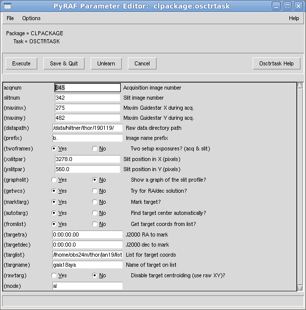
Here's what all these parameters mean, what you need to do to set up now:
- acqnum and slitnum are the exposures that will be analyzed
to find the target and the slit on the chip. These numbers will change with
every new object and can be left alone for now.
- maximx and maximy are the guide camera X and Y coordinates
that the Maxim DL guider was holding the guide star on while the acquisition
exposure (indicated by acqnum) was being taken.
- You do need to fill in the datapath, which is the directory where
the raw data are going to be written (always starting with /data/hiltner, as
of this writing) Include a trailing slash as shown.
- For prefix put in the file prefix used for the data files themselves.
I like very simple ones (e.g. 'b'). Include a trailing dot if you're using
the standard form b.0001, etc. The program will assume the running numbers have
four digits and pad out your input numbers to match.
- For twoframes, check yes unless (a) you know the slit images's
pixel coordinates on the detector exactly and (b) you are sure the slit image won't
shift with telescope position. I don't know if that's true, so I'd leave this as
yes.
- If you take twoframes, then the xslitpar parameter
is ignored, since the slit's X position is measured from the slit image every time.
- However, yslitpar will be the y coordinate for the
object spectrum on the OSMOS detector; you want to avoid the exact center since the
amplifier readouts can cause a discontinuity there.
- The program will analyze the slit exposure and fit a Gaussian to the slit
profile to find its x-coordinate. If you'd like to see a pretty graph of this,
select graphslit. If you do this, it presents the graph and suspends execution
until you close the graph window by clicking on the little "X" in its
corner. It's useful to see it a few times to get confidence in the result, but
you'll probably soon want to de-select this option.
- If you select getwcs, the program will find stars in the image,
attempt to match them to a dense star catalog (PPMXL, derived from USNO-B), and
if a match is found, will derive a World Coordinate System for the image,
which in this case means a transformation from the xy coordinates on the image
to RA and dec. Fits with more than a dozen stars or so and RMS residuals
below about 0.3 A are almost certainly successful
- If marktarg is selected, and the wcs solution is successful, the
program will draw a green circle around the target on ds9.
- If autotarg is selected, the program will run IRAF's centering
algorithms on the target and return precise pixel coordinates. If your
target has very low S/N this may not be accurate.
- If fromlist is selected, the program will go to the list
specified in targlist - which should be the 'all glommed together' list you prepared
earlier -- and look for the target specified by targname, which at
this point has to be perfect case-sensitive match. It will then
use those coordinates for the target marking and centering.
- If you do not specify fromlist, you can type the
colon-separated J2000 coordinates into the fields provided. This is
obviously more tedious and error-prone than giving a name.
- The rawtarg option is for oddly-shaped or very low signal-to-noise objects
that don't centroid well. If you select this option, the task will not
try to refine the object's location with a centroid but rather ask you
to type in the exact pixel coordinates you want. You can get those by
zooming in the ds9 display.
Once you have this set up, in operation you should only need to change
the first four numbers and the name of the object before invoking the
task. And if you use a new directory for each night's raw data, you'll
of course have to update that field as well.
Make some useful prospero scripts.
OSMOS is pretty complicated, and one gets tired and frazzled, so
it can be incredibly easy to take images with the wrong configuration
of slits, dispersers, and filters. I HIGHLY recommend that
you automate some routine actions by making yourself some simple
prospero scripts. This is easy.
Prospero executes scripts that it
finds in the directory /lhome/obs24m/Scripts, so you'll need
to put your scripts there. All scripts have the file extension .pro.
They are invoked from prospero by typing, for example,
call myscript
to the prospero prompt, without the ".pro" suffix.
The Scripts directory has about a million old scripts that people
have dropped there. It's socially responsible to give your own
scripts a distinctive prefix so you don't generate name collisions.
Note carefully that filters, slits etc. the slits, filters, and dispersers
installed in different
wheel positions change from run to run, so you must at the
least check over any scripts you're going to use at the start of your
run, and update wheel numbers as needed.
Here are two that I'll refer to:
#   *** thorblueacq.pro ****
# Get acquisition exposures for osmos inner slit.
# Wheel positions for 2019 January run
#
# Do slit exposure first while acquiring guide star
# open except for 1.2 arcsec inner slit.
#
exp 15
filter1 6
filter2 6
slit 2
disp 2
sleep 5
go
#
# Short direct exposure in V or g
exp 20
# filter2 3
filter1 1
slit 6
sleep 5
go
#
# Leave in place for a confirming exposure if desired.
As you can see, the script first takes an exposure of the slit alone,
which will appear as a bright vertical line in the image. Then it
takes out the slit, inserts a g filter (this is optional --
it's just to give the acquisition image some scientific usefulness),
and takes another exposure.
When you're sure the centering is right, a script like this will
set up for a spectral exposure by inserting the slit and disperser
and withdrawing any filters:
# Set up for a 'science' exposure for blue, inner slit
# Wheel positions for 2019 January run
#
filter1 6
filter2 6
slit 2
disp 1

# Leave the 'go' to the user.
Some notes on the Maxim DL Guider
The 'trick' used to steer the telescope onto the target is to tell the
guide system to center the star on a specific set of XY coordinates on
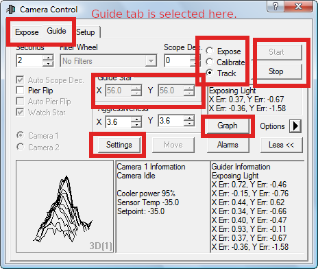
the guide camera. You'll be manipulating the guider a lot, so here's
a cheat sheet outlining (in red!) the controls you'll use most
frequently:
 Salient points:
- Note the Tabs (upper left) that select whether the
camera is in Expose or Guide mode. 'Expose' mode is generally
set to run continuous (throwaway) exposures so you can reconnoiter
and do rough centering. The 'Expose' tab's controls look
different from those of 'Guide' mode, shown here.
- The Guide Star X and Y boxes near the middle are the
heart of the matter -- this is the point toward which the guider
will steer the guide star. You can only type into these boxes
when the guider is not attempting to steer the telescope.
- The Start and Stop buttons on the upper right
have different actions depending on the radiobutton that is
selected (next item).
- The guide-mode radiobuttons labeled 'Expose',
'Calibrate', and 'Track' select which action will be taken when
you hit Start:
- Expose takes a single picture and selects what it thinks
is the brightest star to guide on. Any entries in the Guide Star
X and Y boxes are overwritten.
- Calibrate starts an elaborate song and dance to figure
out the guider feedback parameters, driving the telescope in an
L-shaped figure and noting what the guide star does. We already
know these parameters. Do not select this.
- Track starts guiding; a small part of the chip is
read every second or two and commands are issued to the telescope
to push the guide star into the XY coordinates specified.
(Before slewing to the next target you must Stop the
guider, or else the slew will terminate ungracefully.)
Note that nothing happens until you hit Start; the
radiobuttons simply select.
- You'll want to push the Graph button, which puts up
a little graph showing the guider error signals as a function of
time. This shows you how well the telescope has
settled onto the guide star.
- If you rotate the instrument you'll need to adjust just one
of the Settings - the button pops a new window - namely
the rotator angle used in Maxim DL, which is simply minus the
instrument rotator setting.
OSMOS-specific target acquisition procedure
This is an inherently complicated procedure, and the following list
attempts to break. it. down. into individual steps. It's a
dauntingly long list, but I believe it explains everything. As I noted
earlier, you can save tons of time and tears of frustration
by methodically running this list until you've mastered the procedure.
Once you're not making mistakes, an uneventful acquisition can be
accomplished in something like 5 minutes. If you're getting things
wrong or out of order, this can stretch out considerably.
- Enter your precise target coordinates in
JSkyCalc24mGS. If you
have a target list loaded, you can do this simply by clicking on the object on the
sky display.
- In JSkyCalc24mGS, open the Guide Stars window if it isn't open
already.
- If you're using the inner slit or outer slit, select the corresponding
radiobutton in the Guide Stars window.
- If the instrument rotator is not at zero, enter the
Rotator Angle the box provided and click on the Read Guide Stars
button to refresh.
- If you're using the inner or outer slit, you'll see two sets of coordinates
displayed in the upper right; the green set is that of the center of the
telescope's field, and the yellow set is that of the object, which
is not the same (!), because the inner or outer slit is offset from the center of the field.
(With the rotator at zero, the offset is almost entirely in RA).
- In the JSkyCalc24mGS 2.4m Telescope window, click the
Coords -> TCS Next Object button. The field center coordinates
(not necessarily those of the object!)
will appear in the Next Object line on the MDM TCS display (second from
top). If they don't, try the JSkyCalc Read Guide Stars button and send them
again.
- If the autoguider is running, hit Stop in the guider window.
(The slew will abort ungracefully if the guider is still trying to guide).
- In the MDM TCS telescope control window, hit Start Slew to slew the
telescope. The telescope will start to move; you'll also hear the dome move also
unless it happens to be aligned with the new target already.
- As the slew proceeds, go to the prospero terminal and
type obj 'Tabbys star' or whatever to set the object name.
If there is a blank in the name you MUST include the single quotes.
- Back over in the JSkyCalc guide star window, click on a likely-looking
guide star, ideally toward the left
side of the display. Then hit the Move guide probe button
and confirm in the dialog box. You do this during the slew.
- If you have rotated the instrument since the last target, go to
the Maxim DL guider, be sure the Guide tab is selected,
bring up the Settings window, set the rotation to minus 1 times the
instrument rotator, and click Apply. You can close the settings
window.
- When the slew completes, in the Maxim DL autoguiding computer,
select the Expose tab (not the 'expose' radiobutton under Guide! This
is easy to confuse!), and click on Start to begin continuous
exposures. The guide star should be in the field; if it's not, check the
telescope coordinates and then move the telescope around slightly with the
paddle buttons to look for it. If there other stars aside from
the guide star are visible, their pattern should match that seen in the JSkyCalc
Guide Star window, except rotated by 90 degrees.
-
If you know from experience where the guide star should sit when
the telescope is centered, use the paddle buttons to put the
star near that location, more or less; the aim is to put it close
enough so that it's in the small 'box' the guider reads. Clicking on the window that's
updating brings mouse focus; with that, you can park the mouse near the desired guide
star coordinates and place the star on it for good accuracy, or possibly
use the left mouse button to draw a small target box into which to
put the guide star.
- Once the guide star is in the right part of the field, Stop the continuous
exposures in Maxim DL, and switch to the Guide Tab.
- If your slit and rotation is the same as last time, and you've
positioned the guide star near where it was last time, simply select the
Track radiobutton and Start to start guiding. The window
showing the guide field will shrink to a little postage stamp and the
guide star will drift toward the center. Once it's settled, the telescope is
locked to the sky. [Note: I generally keep the Maxim DL guider's
Graphs open all the time. You can see the guide star settle down
by watching that.].
- If you really don't know where the guide star should sit,
click on the
Expose radiobutton, and hit Start. This takes a single frame,
selects the brightest star as the guide star, and writes its pixel
coordinates in the Guide Star X and Y fields. Check to be
sure the X and Y are for the star you want; if they're not,
just left-click on the correct star and its coordinates will appear in
the X and Y fields. Once you have the guide star
X and Y in place select the track radiobutton and h
it Start, as in the previous step.
- The next steps take direct and slit-only exposures;
The prospero script thorblueacq.pro given above will do this, though
as noted you'll no doubt have to update it to reflect whatever wheel
positions your desired slits and filters are in.
(Note: If you're using the center slit,
it should be possible to speed up the readout of the
acuqisition and slit exposures by using the 1k square
region of interest. HOWEVER, osctrtask is at present set up
to look for the center slit near X = 2000, where it appears
in a 4x1k image. If you consistently revert to 1k roi for
the slit and aquisition exposures in the center slit, you
can hack your way around this by finding the line definining
the roughslitx quantity, and substituting 500 for the
entry for the center slit; after you've saved the file,
do pyexecute('osctrtask.py') again to load the modified script.
Of course, you'll still need to call roi4x1k for the science
exposures.)
If you don't have a script prepared and
need to take these exposures `by hand' do the following in Prospero:
- Take the slit exposure:
- Take out all filters with the filter1 and filter 2 commands
- Take out the disperser
- Insert the slit you're using.
- Take a 15 second exposure.
- Now take the direct exposure:
- Optionally insert a filter to give it some scientific usefulness
- Remove the slit
- Take a 20-sec exposure.
Pro tip: With a script, you can start this process while the
telescope is still settling on the guide star; the slit exposure
need not be accurately centered. The telescope will have settled
accurately before the direct exposure is taken -- that's the one
that does need to be centered.
While those exposures are running, you can epar osctrtask
over in your pyraf window. The things that usually need changing are:
- The numbers for the acquisition and slit images;
- The X and Y coordinates in use from Maxim DL;
- The name of the target on the list.
Once the last setup exposures has read out, execute osctrtask either
from the Execute button in the epar window or by typing 'osctr' to
the pyraf prompt.
osctrtask will execute in the terminal you're using for pyraf.
It produces a huge amount of verbiage. If all goes well, it will
auto-find the slit, auto-match the stars in the field to a catalog,
find your target based on its celestial coordinates, and then
type out the new X and Y coordinates to enter
into the Maxim DL guider. Along the way you have to hit Enter
once, when it asks for which ds9 frame to use. This is unimportant.
If the target does not auto-find, you have to mark it in ds9.
In this case the task invokes IRAF's imexamine for you, which
pops a little 'blinking donut' cursor on ds9 and expects input in the
form of characters you type marking features on the image.
- If ds9 is showing the slit image, select "frame", and "next" or
"previous" to bring up the star image.
- If the star image is all black, go into the "Scale" menu and select
"zscale" to change the stretch.
- In the Zoom menu, be sure Invert Y is selected.
Otherwise the image will be 'upside down' with the wrong parity.
- Find your target; place the mouse dead on it and hit 'a'. You
will get no feedback, which is unnerving.
- Type 'q' to quit the imexamine mode.
The program proceeds to parse a little scratch file of your responses,
which pyraf and ds9 wrote behind the scenes. The task should then
proceed to completion and give an answer.
Re-center the telescope by changing the pixel coordinates that the
Maxim DL autoguider is trying to maintain:
- Hit Stop on the Maxim DL autoguider.
- In Maxim DL, replace the X and Y guide star coordinates with the numbers produced by osctrtask.
(If you forgot to update the XY coordinates in osctrtask when you took the setup pictures,
note that osctrtask also supplies deltas, so you can figure out the new XY.)
- Note that the X coordinate is across the slit and critical; Y is along the slit and less critical.
- If the offset is less than about 30 pixels, simply Start the guider. The star should still be in the postage stamp, and the star will recenter.
- If the offset is greater, the procedure to get the guide star into the right place is similar
to what you just did, to wit:
- Select the Expose Tab in Maxim DL -- not the
radiobutton in the guide tab!!
- hit Start to begin exposing
- click on the updating image window so it displays cursor XY coordinates. Park the cursor near the coordinates you want, or
draw a little box to guide yourself (left mouse button).
- Using the telscope hand paddle, move the telescope to put the guide
star near its new nominal coordinates.
- In Maxim DL, hit stop to stop the continuous exposures..
- In Maxim DL, Select the Guide tab. In this, be sure that the track radiobutton is selected.
- Now hit Start; the star should be somewhere in the guider's little postage stamp window, and will settle
into its new position (unless you rotated the instrument and forgot to change the rotation angle in
Maxim DL, in which case it can drift away.)
I recommend that you check the centering by taking another acquisition picture.
You need to wait for the guider to settle to the new position before doing this. There's no
need to take a second slit image -- in fact, if you took the acquisition image second,
OSMOS should still be all set up to take another one.
To process this exposure all you need to do in osctrtask is change the number
of the acquisition exposure, and update the Maxim XY values to their new ones before running
the task again. If the analysis yields a delta-X of one guider pixel or less, you can safely ignore it --
as noted, a pixel on the guide camera subtends only 0.223 arcsec.
Once you've fine-tuned the centering, you're finally ready to take a spectrum --
the telescope is locked on a guide star, and your target will fall exactly on the slit.
To take the spectrum:
- Remove unwanted filters from the beam; insert an order-blocker if needed for your setup(e.g. OG590).
- Insert the desired slit.
- Insert the desired disperser.
- Very likely, set a longer exposure time by typing (for example) exp 600 to Prospero.
- Type go for a single exposure, or (for example) go 3 to take 3.
Note again that a script (e.g. "thorbluespec.pro" above) can make this less error prone.
It does not set the exposure time or start the exposures, though.
What osctrtask does (in brief) :
- Bias-subtracts the acquisition image and (optionally)
the slit image, and loads them into images named
acqimage and slitimage. These names are
fixed, and the contents of acqimage (and slitimage
if it is selected) are overwritten every time the task is run.
- Runs a number of 'sanity checks' to be sure the
instrument was configured correctly for the exposures.
- Displays the image(s) on the ds9 image display, in frames
1 and 2 if there are two of them.
- Obtains the pixel coordinates of the target on
acqimage, mostly by matching the detected stars to a catalog
and inferring the location of the target in the image.
- Obtains the pixel coordinates of the slit, generally
by fitting its image automatically. It knows which slit
to look for from the header coordinates.
- Using the pixel coordinates of the image and slit,
computers the Maxim DL guide star pixel coordinates that will
put the target in the slit.
Note that the script leaves the original data untouched -- you
needn't be afraid of it screwing anything up.
MOSTLY OBSOLETE MATERIAL FOLLOWS.
It's marked off by the color of the type. I haven't deleted it all
because some of the esoteric discussion of centering still applies.
Quick Instructions:
You should be logged on as obs24m on mdm24ws1 (or ws2).
Task Parameters and Options
Here's a screenshot of the 'epar' for osctrtask.
The first four parameters tell osctrtask where to
get the data. Note that the datapath requires a
final slash, and the prefix requires a final dot (which
is nearly invisible here). acqnum and slitnum
are the exposure numbers for the two images; you need to
give something for slitnum even if you're not using it.
These are internally converted to the standard four-digit
format.
In the case shown here, the program would go looking for the
original acquisition image as
/data/hiltner/160823.0692.fits
If the program fails immediately, there's probably something
wrong with the path or prefix. The program assumes that the
image number is padded with zeros to have 4 digits, as is standard.
For the bare-bones use of the program,
You'll find the bare-bones use to be a bit labor-intensive, and
there's considerable ease and efficiency to be gained by using the
other features of the program, as follows.
slit -- This must be 'inner', 'center', or 'outer'. This
parameter is only used to show you the region of interest in the
ds9 display.
slitns -- In the comissioning runs (spring 2010), OSMOS
was mounted so that the slits were east-west. To minimize
atmospheric dispersion
near the meridian, one wants the slits
north-south by default, and that has been adopted as standard
for some time now. If for some reason OSMOS is mounted at
90 degrees to this, deselect this.
twoframes, xslitpar and yslitpar -- If you are using a
fresh exposure to locate the slit, set twoframes to Yes.
If you're using a nominal slit position from a previous exposure,
de-select twoframes and type the
X and Y pixel coordinates of your slit location into the
xslitpar and yslitpar boxes. If you do this,
use caution -- the X coordinate needs to be accurate to around
one pixel!
The next nine (!) parameters control automatic target
finding. This doesn't always work, but when it does it is a
tremendous convenience.
getwcs -- If this is checked, the program will
find star images in the acqimage and attempt to match them to
entries in a compact version of the PPMXL
astrometric catalog stored on disk. If this appears to work, the
world coordinate system
parameters will be set in acqimage's header,
in which case you know the precise RA and dec for every
point in the image.
marktarg -- If this is selected, then if the wcs is
successfully found, and
you supply target coordinates, your target will be marked
with a circle on the ds9 display.
autotarg -- If this is selected and the wcs is
successfully found, and you supply target coordinates, the
centroid of the target will be found automatically
(by automatically running the IRAF imexam command 'a').
Otherwise, you'll have to type 'a' yourself (see below),
or enter the coordinates manually if autocentering
will converge on the wrong object (a problem if your target
is the fainter member of a close pair)..
There are two ways to feed in the nominal RA and dec of
the target, so the program can mark and/or centroid it
on the image:
- If fromlist is 'Yes', then the list specified by
targlist is searched for an object with the exact
name given by targname (it has to be a perfect,
case-senstive match).
The targlist is in the
same format used by the TCS, namely
name_no_blanks  rah ram ras   decd decm decs  equinox
for example:
Feige98          14 38 15.76  +27 29 32.9  2000.0
Note that if your list is in some other directory than the one
you're working in, you'll have to give the full pathname, as
in the example shown.
- If fromlist is 'No',
then the targetra and targetdec are read;
they must be J2000. The format for targetra and
targetdec is fairly forgiving -- you can use
spaces instead of colons.
Finally, there's the rawtarg parameter, which
turns off the centroiding of the target. This is useful
if, for example, you're centering on a faint object with
a nearby bright companion. In this case, inspect the
acquisition image to find the X and Y pixel coordinates
you want, and type them in when the program prompts you.
The pushprobe parameter is not implemented.
Marking the images interactively
When you run osctrtask, the acqimage (and
optionally the slitimage) are automatically
displayed in ds9; acqimage is in Frame 1, and
slitimage (if any) is in Frame 2. You will need
to use ds9's Frame commands 'next' and/or 'previous'
to bring up the appropriate image.
Unless you're autocentroiding the target and
using a previous slit position, you will
need to mark one or two positions on these images using
a cursor. To get these positions, the program runs
the IRAF imexam task and parses the output.
Unfortunately, the programming trick used makes it impossible
to see the results as you go along
-- when you mark the target, or the slit,
nothing happens. This is awkward and disconcerting, but
it's normal (and apparently inevitable).
Note that when imexam is alive, you get a
"blinking life preserver" cursor in ds9 --
if you have an arrow cursor instead, then
imexam is not in control yet.
A common reason for this is that there's an
unanswered prompt in the window where you're running pyraf
- possibly something like "Display frame [1]:"
Just hit enter to keep it happy, and you should get the
blinking life preserver in ds9, and be able to proceed.
Depending on what the program needs, it will tell you
to mark the slit with an 'x', the object with an
'a', or both.
-
The slit location, if needed, needs to be marked very
accurately (sub pixel) in the cross-slit direction.
To attain this accuracy you may need to use the Zoom
commands in ds9 (and the center mouse button to recenter
the image) to blow up the slit to adequate scale.
You may want to fiddle with the image stretch -- that's
in the scale top-bar menu. The Scale parameters ...
choice at the bottom pops a nice window that gives great
control over the stretch -- it's good not to have the
slit pure white.
Once you have enough scale and a good stretch,
position the life-preserver cursor dead in the middle
of the slit and type 'x'. As noted above, you won't
get immediate feedback,
but it should be doing the right thing.
- The target location, if needed, is marked with
an 'a', which finds the image centroid, so you
don't need to be quite as fussy.
To do this, change frames to show the
acquisition image, find your target (which will
have been circled if the wcs finding was selected and
working), zoom in on the target, put the cursor on the
star, and type 'a'. Again, you won't see anything,
but your answer should have been recorded.
You won't need to mark the target if you specified
auto-find and auto-center appeared to work, or if you're
using rawtarg, in which case you'll have to note
and type in the coordinates at the prompt.
- Once you've marked everything you need to,
type 'q' to quit the imexam cursor. If the program
has the information it needs, it should finish.
If not, it should ask you again.
- Note that the distinction between 'x' and 'a' is
key -- they produce different-format output, and this is
used to distinguish the slit and the star. Also,
'a' autocenters the star and reports those coordinates,
while 'x' reports the exact pixel coordinates you
marked.
- If you need to select a member of a close double,
or it's not appropriate to centroid the target for
some reason, set the rawtarg flag to Yes.
Then, you'll be prompted to type in the X and
Y pixel coordinates you want.
- Among the last things the program reports before
it quits are the X and Y locations of the slit. If you
have determined these interactively, you may be able
to get away with copying them
into xlitpar and yslitpar and
dispense with the slit exposure on the next setup.
Doing so assumes that the projection of the slit
on the detector does not move; the manual says this
is the case, but I for one have not adopted this
practice.
Advice and Miscellany
All these procedures go better if you have really
accurate target coordinates, good to the
sub-arcsecond level. The JSkyCalc24mGS program that
moves the guide probe uses the UCAC3 as the base
catalog, and the guide star coordinates are updated
for proper motion, so their coordinates are
typically good to less than 0.1 arcsec.
Experience has shown that the center of the 'center'
slit is not perfectly aligned with the guide probe
coordinate system. In our 2010 September run, we
adopted the practice of applying an extra offset of
dx = -180, dy = -100 to the JSkyCalc24mGS coordinates --
basically, we just moved the guide probe using
JSkyCalc24mGS, then manually made the small extra move
using the dx and dy boxes in the xmis window, and
then centered the guide star and started guiding.
We always used the same nominal guide star pixel coordinates
in the Maxim DL guide software, and with accurate
target coordinates the stars were already in the slit
(though not necessarily dead-center).
It's important to be aware that in the Maxim DL system,
if you're in the GUIDE tab and have the
expose radiobutton selected, then when you
hit Go, the camera will take an exposure and the
nominal camera XY coords for the guide star will be
reset. This is OK when you first set up on the
field, but for subsequent centering steps you'll want
to control changes in the nominal XY coordinates manually.
The OSMOS manual claims that once the slits have been
installed in the filter wheel, their projected locations
on the detector are very steady. For this reason, I've
offered the option of re-using the slit position,
by turning off twoframes and supplying the
appropriate slitxpar and slitypar. It might
be best to treat this claim cautiously,
especially if your program calls for observations at funny telescope
positions or rotator angles.
In order for the getwcs option to work, you need
accurate telescope coordinates -- within
20 or 30 arcsec, ideally. These should be the coordinates
of the field center, not an offset slit.
The JSkyCalc24mGS program provides field center
coordinates for the offset slits, even if you have the
instrument rotated. If you need to rezero the
telescope coordinates, be sure to insert the appropriate
field center coordinates in the RA and dec
boxes in xtcs, and then carefully check
that the RA and dec have reset to the correct values
before moving away. If you blunder when you
re-zero coordinates, and move away before you realize
your mistake, you have a real mess on your hands, so be
careful. (The 2.4m user's guide, on the
mountaintop
web server, has
a section on 'how to restore lost pointing').
Note that the only places you need to account for the
image rotator are in the JSkyCalc24mGS guide star selector,
and in the MaximDL rotation setting -- once the instrument is mounted,
the guide stage rotates with the instrument, so they're
in the same frame. However, mounting the instrument
at a different angle does affect the relation between
the guide stage and the instrument; that's the reason
we need the slitns parameter.
Because the 4x1k readout option is long and skinny
the star-matching algorithms
read a strip of the catalog that should
coincide with the field of view, more or less. This
involved a rewrite of the star-matching software, which
had assumed that the field is a square patch. The star-matching
software needs to know both the mounting choice and the
instrument rotator, but it gets the instrument rotator from
the image header.
The bias-subtraction scheme splits the image into four
pieces, bias-subtracts each piece, and then pastes the
pieces back together. In the process, any header information
that is not explictly copied into the new image is lost.
I have copied some of the most informative header parameters
into the new images -- title, ra, dec, filter and so on --
but beware that much of the header information will be missing from
acqimage and slitimage.
----------------------------------------------------------------------
Footote: What is the world coordinate system?
The WCS refers to the "real" coordinates in an image, e.g, the
RA and dec rather than the XY pixel coordinates. An image
with WCS has keywords written into the header that express the
transformation from XY to "real" coordinates (in this case
RA and dec). DS9 can interpret WCS, so when the WCS in
an image is set, and it's displayed in DS9
the RA and dec that show in DS9 are the real RA and dec,
not some lame guess.
Important note: DS9 is only 'wcs-aware' if
you use its own 'File' menu to display images. If instead
you use 'display' from within IRAF, nearly all the
header information is lost. In addition, all the
dynamic range is lost because IRAF was written in the
dark ages of 256-level displays; if you use display
from within IRAF, it forcibly maps the original
image into a fake 8-bit image, and then displays the
fake image. There is no good reason to display
from within IRAF -- imexam and the like work fine
if you don't -- and it basically cripples DS9. Make it
a practice NEVER to display an image from within IRAF. Instead,
use the File pull-down menu in ds9, and choose
Open and use the dialog box. You'll never go back.
[Back to wcs
loading discussion ... ]
------------------------------
If it fails ...
This way of setting up a pyraf task depends on the existence
of a parameter file, which is
a short file that gives the names of the parameter, their
data types, default values, and so on.
The file must be named
/lhome/obs24m/iraf/uparm/osctrtask.par
If this is corrupted for some reason, you can grab a fresh
copy by getting into the /lhome/obs24m/iraf/uparm directory, and
typing
cp /usr/local/pkg/thorsoft/scripts/osctrtask.par .
[Don't overlook the final dot.]
Once you're sure you have a fresh parameter file in the right spot,
go back to where you were working within pyraf (restart
if need be), and repeat the
pyexecute('osctrtask.py')
command. Now, it should work.
[Back to the instructions.]
Other Useful OSMOS tasks: Once you've successfully taken a spectrum, there is a
program called osqlsp that will give you a properly bias-subtracted,
optimally extracted, sky-subtracted, and (optionally) wavelength-calibrated
version for quick-look. This is not documented separately, but it is
functionally almost identical to the qccds program for CCDS
spectra. You should
be able to use the
qccds documentation to run this; just substitute 'osqlsp' for
'qccds' in the instructions.
For direct images, the task osbias is very useful.
It subtracts the bias strips, reassembles the four images, and
attempts to find a World Coordinate System solution and mark your
target right on the image. You can get this in just the same
way as osctrtask -- follow the same instructions as below
for making a local copy and doing the pyexecute to make
pyraf aware of the task.