Appendix : Jules Halpern's notes on guiding the 1.3m.
The MDM telescopes point pretty accurately, but not to arcsecond accuracy. They track pretty well, but exposures longer than a minute or so are likely to be trailed. It's therefore important to be able to acquire objects and guide the telescope. This document describes how to do this.
Because the telescopes are on equatorial mounts, the field does not rotate on the focal plane as the telescope tracks across the sky. This is a great simplification.
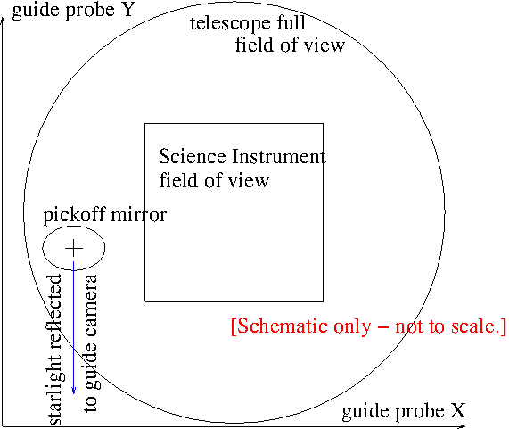
To keep the telescope from drifting off target as it tracks, the usual strategy is to use an offset guide star. This is a star in some part of the focal plane away from the science field of view, which is reflected by a "pickoff mirror", mounted on a movable guide probe), through some optics into a guide camera. An autoguiding program watches the guide star, and if it appears to drift -- indicating that the telescope is going off-target -- it sends a correcting signal to the telescope. With proper tuning, this can be very accurate, holding the telescope at a constant celestial position to within a fraction of an arcsecond. Such accuracy is necessary for good direct imaging, and is also very desirable for spectroscopy.
The figure below is a sketch of the telescope focal plane (the 2.4m and 1.3m are similar). The pickoff mirror is mounted on the guide probe, which moves on an XY stage as shown. The pickoff mirror is above the science instrument (it's in the Multiple Instrument System (MIS) guider unit), so it can't collide with the science instrument; however, it can block the science instrument field of view. This can be a useful capability (e.g. for finding a bright star when you're lost), but it's important to retract it into a safe position when you're taking data.
1.1 : First night with a newly-changed instrument:
1.2 : Two target-acquisition "philosophies
When you acquire a guide star in the FLI camera, you have two choices for acquiring your target:
If you have an instrument where you can quickly see your target and center it -- e.g. CCDS or Modspec -- this may be the most efficient strategy. If you have a long-reading camera of some kind (e.g. direct imaging or OSMOS) you may want to use the guide-probe method detailed below.
angle = -1 * rotator angle for the 2.4m.
If your instrument reads out slowly, it takes a while to center up your target. A faster procedure is to set the guider where you know a guide star will be when you center on your target, and then center on the guide star using the guide camera, which reads out quickly. Basically, you follow steps (1) through (4) above, but then you move the telescope to put the guide star in its nominal position on the guider, and start guiding. Step-by-step instructions for this method are given here.
Suppose you need to make tiny offsets, for example to center a target exactly in the slit. In principle, making small steps with the guide probe should do this -- move the probe a bit, and the telescope will follow eventually (there are about 12 motor steps per arcsec). However, as of 2014 June there appears to be just enough stiction -- or something! -- in the guide probe mechanism to make this a bit problematic. I am now recommending changing the XY pixel coordinates slightly in Maxim DL instead. To do this:
The guide cameras on both telescopes were built by Finger Lakes Instruments, and are operated using Maxim DL software, which provides autoguiding capability.
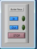
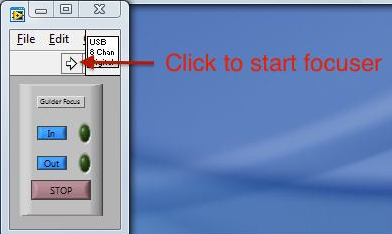
2.1 : Camera Startup Procedure.
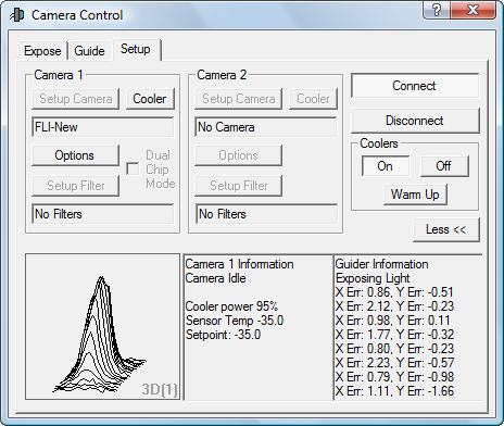
2.1.1 : Hidden Guider Parameters
The guider has a couple of hidden parameters that are
sometimes left in less-than-ideal states. They are:
2.1.2 : Port for Autoguider Output
If for some reason Maxim DL gets reset to its default values, then you have to tell it which of many methods it should use to control the telescope. You do this on the Settings window (again), in the Autoguider Control box, using Control Via pull-down menu; you want:
ASCOM Direct for the 2.4m or
LPT378 for the 1.3m
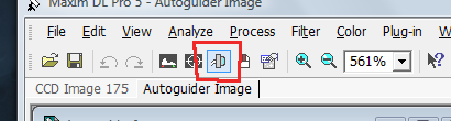
2.2 : Manipulating the Image Display
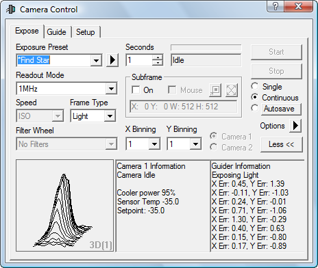
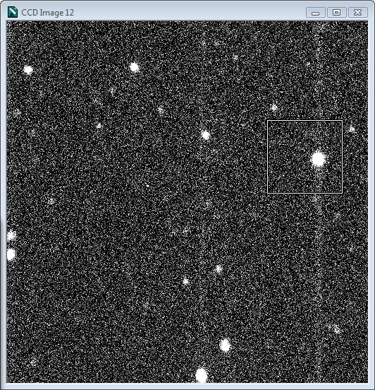
Above: A sample 512-square frame from the Expose control. The faint vertical stripes are probably due to the fact that we're operating without a shutter, so that the bright star 'paints' those pixels during the (very fast) read cycle.]
Here are some things you can do to change the display:
What you're seeing: In the standard orientation of the FLI camera, with the instrument rotator at zero, the guide field appears with North at the top and East to the left. This is rotated by 90 degrees from the guider cartoon in JSkyCalc. At the 2.4 m the scale is 0.223 arcsec per pixel , so that the whole 512-square field subtends 114 arcsec. However, the corners are vignetted -- especially the upper left -- so the useful field is somewhat smaller. [At the 1.3m, the field should be larger, but as of this writing it has not been measured directly.]
[This is organized a little awkwardly, having been pasted from another document. Read this and the section on Establishing offsets at the start of your run and it should all become pretty clear.]
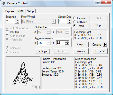
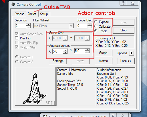
In the guide tab there are three important options in the buttons on the right - Expose, Calibrate, and Track.
Some notes about the user interface and nomenclature:
If you select the Expose radiobutton under the Guide tab, and hit Start, then:
In the Options menu (right side of the box) there's a control for Track box size. 64 pixels seems to be a good option. The track box needs to be contained entirely within the image, so the guide star can't be close to the edge of the field.
The guider has to know how quickly the telescope will move when it hits the buttons, and in which direction. There's an autocalibration procedure for this which is not recommended -- it's not necessary. For completeness, it's described later in greyed-out text.
It's quickest to simply set the guide parameters by hand. In the Guider Settings window, at the lower left, under Manual Calibration, simply set:
For the 2.4m:
X Speed = -7.8, Y Speed = -7.3, Angle (deg) = 0 for the 2.4m
X Speed = -8, Y Speed = +8, Angle (deg) = -90 for the 1.3m
At the 1.3m similar speeds are obained if the paddle gain is 0.02; you set this by going to the box on the telescope control GUI provided for typed input, and typing
tx paddle gain=0.02followed by "enter". Be sure to do this every day, since the paddle gain is often set higher by people needing to move the telescope faster. Also, it may change to some other value if the TCS is restarted.
Note that the 1.3m TCS does not have a "Cos Dec" option that automatically increases the EW speed far from the equator. To account for this use the "Scope Dec" parameter in the Guide tab. Jules Halpern of Columbia contributed some draft notes (reproduced below) on guiding the 1.3m, which describes in detail the procedures that are particular to the 1.3m, and gives more precise values for the speeds.
If you rotate the instrument (very seldom done on the 1.3m), change the Angle parameter to adjust for the rotation. The formula is
NOTE: the calibration procedure described in the greyed-out text below is deprecated at the 2.4m -- it is not working correctly as of 2014 January, apparently because a hot pixel is causing it to get confused. It is unnecessary in any case.
The 1.3m camera may not have this problem; Jules Halpern's notes discuss some considerations for calibrating the 1.3m guider, in the event it's needed.
Now you can move on to the Calibrate button. This automatically establishes the scale, orientation, and parity of the camera image, and the sensitivity of the guide buttons, so that the program knows what buttons to push to bring the star back when it drifts. Note that you probably only need to do this at the start of your run; you may even be able to skip this if you know nothing changed since the last observer. Note especially that you don't have to recalibrate the guider at every new target; doing so is a waste of time.
You're finally ready to guide!
2.4 : Establishing Offsets at the Start of the Run.
Here's a procedure to get you going.

Now you're all set up.
2.5 : Acquiring targets by offset.
This is especially appropriate if your instrument reads slowly, so that it's awkward to center your target by simply looking at it. The basic idea is to put the guide probe where you know the guide star will be, and then center using the guide camera:
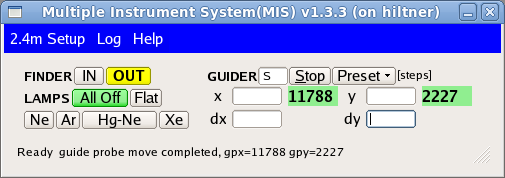
As noted earlier, if the center of your instrument's field is offset from the nominal center of the guide field, you'll have to adjust for this, because JSkyCalc's nominal coordinates won't be quite right.. One way to do this is to offset the guide probe away from the JSkyCalc coordinates every time you set on a new object, by manually entering dx and dy into xmis. This is tedious and error prone.
It's easier in the long run to build this into the calculation, using the provision in JSkyCalc. Suppose you have already determined the dx and dy values for your instrument. Install them as follows:
That's not a misprint - the X offset depends on dy, and the Y offset depends on dx.
Now that you have non-zero numbers in those fields, when you read guide stars, you'll two sets of coordinates in the selector -- the yellow numbers are for the target, and the green the nominal center. A yellow box marks the target's off-center location in the diagram.
Guide star coords are not with respect to full frame. I've seen Maxim get into a state where it reads a subframe while guiding, and then the guide star coordinates are not with respect to the full frame. In principle it's faster to read a subframe, but in practice the read is fast enough that it makes no difference. To cure this, In the guide tab, in the Settings pop-up window, lower right side, in the Exposure Settings sub-box, hit the Reset button, and then the OK button so that it 'takes'. It may not look as if it has, if you've zoomed the guider image display to see only the guide box; just de-zoom with the mouse wheel to see the whole field.
                                                   February 9, 2014

 ===================================================================
 Supplemental notes on autoguiding at the 1.3m, with help from the
 Maxim DL User Manual; some of this would apply to the 2.4m as well.
 ===================================================================

This writeup assumes that you are already familiar with John Thorstensen's
manual on Autoguiding at MDM, therefore, with the basic operation of the
Maxim DL guiding system.

If you or the autoguider (figuratively) depress a guide button on the
hand paddle. the telescope will move a certain number of arcseconds
per second (the guide rate).  This is also what happens during the
Calibrate function of the guider.  If you use the Calibrate function
at the 1.3m, as described below, you should do it with a star on the
celestial equator, and enter 0 in the "Scope Dec" field at the top center
of the Guide window.  This is necessary because the 1.3m TCS does not
adjust the HA guide rate for declination; the EW guide motions are slower
across the sky at high absolute values of the declination.  By the same
token, the guider doesn't know at what declination you are pointed unless
you tell it.  So you have to enter manually the declination in the
"Scope Dec" field of the Guide window each time you move to a new target.
The guider will use the declination to adjust how long it presses the buttons.

Moral: at the 1.3m, YOU have to tell the autoguider what the declination is.
(At the 2.4m, ignore the "Scope Dec" feature of guider because the TCS takes
care of it. The 2.4m guider always sees the same speed in pixel units.)

Here. we refer to the telescope guide "rate" in arcseconds per second, while
a guide "speed" is in pixels per second, the pixel of the autoguider CCD.

Automatic calibration is optional
---------------------------------

In order to get an accurate calibration, the telescope should move at
least 20 pixels in each of X and Y.  The length of the move will be
proportional to the product of the "Cal time", which you enter in the
Settings pop-up of the Guide window, and the paddle gain, which you set
in the Command line of the TCS Control Panel (running on mcgraw).
The "Cal time" is how long the guider will press the guide buttons to
determine the guide speeds.  The default Cal times are 5 seconds in both
X and Y, and the recommended paddle gain is 0.02.  To see or change
the paddle gain, type in the Command line of the TCS:

     tx paddle gain       (to see what it is)

     tx paddle gain=0.02  (to set it)

Moral: The guide speeds are only valid in conjunction with a particular
paddle gain.

Check the paddle gain at the beginning of each night, as the staff
may have increased it to slew rate if they were working on the
telescope during the day.  Also, any time you restart the TCS, the
paddle gain may reset to a default value.  The last time I restarted
the TCS it came up with paddle gain=0.01, which is not a bad value to
use.  But you would have to calibrate the guider for that gain if that
is what you are going to use.

For paddle gain=0.02 and Cal time of 5 seconds, the calibration should
give the following speeds AT THE CELESTIAL EQUATOR.  The values are only
repeatable to +/-0.5 and are rounded off here to that level of precision:

     X Speed  -8.5
     Y Speed  +6.5
       Angle  -90

Remember that these speeds are in pixels per second, so it implies that the
telescope moved about 30-40 pixels during the calibration, which is good
enough.

Sometimes the calibration will fail because of backlash in declination;
the telescope may not move in declination (X) even if the guide signal
is activated for 5 seconds.  If this occurs, a little error message
will pop up to the effect that the star moved less than 5 pixels in X,
and you will see that the speeds were not updated. If this persists
after several tries, you could try increasing the Cal time to 10 seconds
to get it to move.  It's okay to do this as long as it doesn't cause the
star to move completely off the field.  However, you may never take out
the backlash (more on this below), so you may not get a reliable result.
As a last resort, just manually enter the above values, and they should
work well enough, providing that you also set the paddle gain to 0.02.

Manual calibration is preferred
-------------------------------

Now that you understand how the fancy auto-calibration works, and
why it can fail at the 1.3m, you may realize that the guide speeds
can be determined during the day by using the physical hand paddle,
the clock, and the coordinates on the TCS GUI.  In fact, the values
that I tabulated above were determined in this way, and are consistent
with what the guider measured by itself on the sky.  You could just
adopt these parameters (including paddle gain=0.02), and stop reading
here.  I only really wanted the calibrate function of the guider
to determine the signs of the Speeds and the Angle, which I would
otherwise have to guess.  To calculate the calibration, I just had
to know the pixel scale of the guider CCD, which is 0.67", to convert
the speeds that I measured into pixels per second.  I have only
determined the pixel scale to within about 10%.  It should be possible
to be more accurate, but I haven't done that yet.

Aggressiveness is not a virtue
------------------------------

An exposure time of 2 seconds for guiding works pretty well.
The recommended value of "Aggressiveness" is 4-5. Aggressiveness is the
fraction of the calculated offset that it actually corrects, with 10
being the full move.  So 4-5 is a conservative amount that prevents
overshoot.  Overshoot causes an oscillation at a small multiple of the
period of the guide exposure, with an amplitude of +/- a couple of pixels.
(In normal guiding, with good seeing and no wind, the typical errors
can be 0.1-0.2 pixels.)  If the guider appears to be oscillating,
first check that the paddle gain is correct for the guide speeds that
you are using.  As a second resort, reduce the Aggressiveness.
Make these changes to avoid chasing after momentarily jumping images
when the seeing is bad or when wind buffets the telescope.

"Nodding" is not bad guiding
----------------------------

An oscillation caused by the guider is NOT the same as the intermittent
"nodding" behavior of the 1.3m, which is a feature of the TCS alone.
It's easy to tell the difference.  A guider-induced oscillation will stop
as soon as you stop guiding.  On the other hand, if the TCS is nodding,
it is a more pernicious effect that occurs whether or not you are guiding.
The TCS nodding can manifest itself as repeated jumps of 10"-60" that
quickly return to the original position.  Or it can be a jump followed
by a return in several discrete steps.  Or an oscillation of smaller
amplitude that is more-or-less continuous.  These motions occur only in
declination.  The guider is not capable of compensating for the nodding.
The user can't prevent such nodding either, except perhaps by wishing,
but more often by moving to another part of the sky.

Backlash is unpredictable
-------------------------

Sometimes backlash in declination will prevent the guider from correcting
for many cycles, up to a few minutes.  The telescope will drift away by
a couple of pixels in declination before eventually coming back.  That's
when your lack of aggressiveness becomes a handicap,  because it takes
a longer time to take up the backlash.  There is a Backlash parameter
in the Guider Settings next to the Speeds.  It units are seconds, and it
is supposed to account for the time delay due to backlash in exactly the
way that you might imagine.  It presses the button for that much extra time
that it takes to start the telescope moving.  Backlash is usually a problem
in declination but not in RA.  However, you should probably set both backlash
times to zero unless you are exactly sure about the behavior of the telescope,
which I'll bet you aren't.  The 1.3m backlash is intermittent, and sensitive
to the mechanical adjustment of the telescope as well.

Conflicting coordinate conventions are confusing
------------------------------------------------

The guider image is oriented such that North is up, and East is to the left.
The X coordinate increases to the West (right), and Y increases to the South
(down) as you pan the cursor across the image.  This is for the default
telescope rotator position of 0 degrees, and applies at both telescopes.
The Guide Star X,Y coordinates and the scrolling X Err and Y Err
in the Guider Information window are consistent with this convention.
The sign of the error is the direction that the star moved.  However,
the points plotted in the Tracking Error Graph have X and Y switched
from the image coordinates, and one of their signs is reversed, too.
X Err is graphed as -(Y Error) and Y Err is graphed as X Error.  So you
have to look at the X Error graph to see errors in declination.  If you're
confused now, join the club.  These conflicting coordinate conventions
appear to be an unfortunate design feature.

This raises the question of which coordinate system applies to the
Speeds and the Aggressiveness, which are the properties you can evaluate
and modify.  The X Speed is for declination because that's the one that
usually fails  in the self-calibration.  And the guide rates determined
"by hand" for RA and declination are different; their magnitudes are
consistent with X Speed being for declination.  So X Aggressiveness
is probably also for declination.   In summary, the graph's coordinates
are correct and the image's are not, if that helps you think about this.