10 The Primary Mirror Air-Conditioning System
The primary mirror is cooled to reduce the effect of "mirror seeing". When the mirror is warmer than the ambient air temperature, currents can deteriorate the seeing, adding 0.4" for every 1 C. The mirror should ideally be slightly cooler than the ambient air but when this condition cannot be met it is best to have the mirror considerably cooler than ambient. The best seeing is obtained when the dome air is continuously flushed with the ambient air. Make sure that the louvers and garage door are fully open and that the passageway doors are closed.
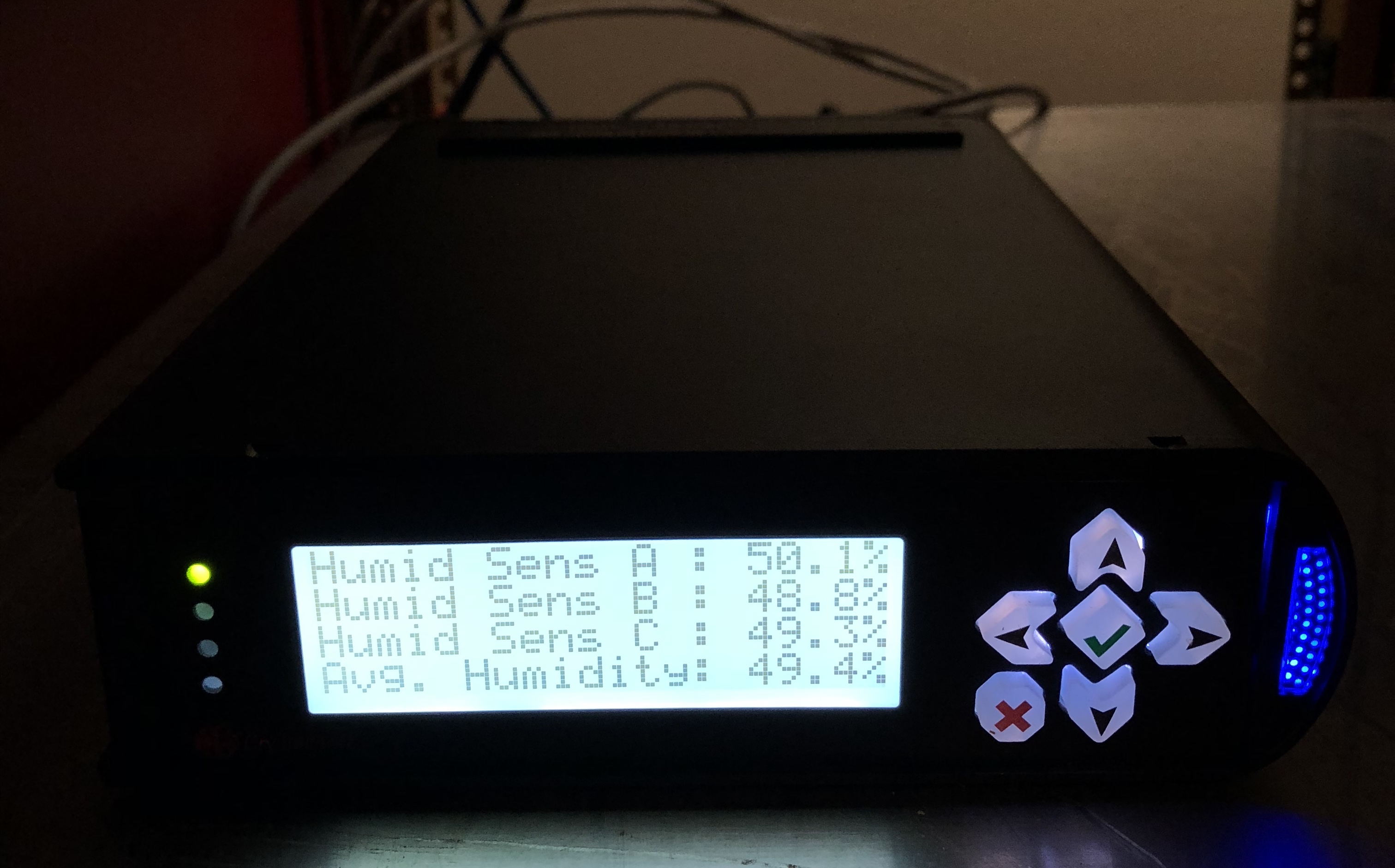
The environment of the telescope and the ambient dome air are monitored by seven digital temperature sensors and three humidity sensors.
The following points are monitored:
The air-conditioning unit is located outside to the south-east corner of the dome. This unit cools the refrigerant, turning it into a liquid. The cold liquid is then pumped to a series of coils located under the dome floor. A fan draws ambient dome air in through a floor register (located to the east of the telescope), passing across the cold coils, and reaches the primary mirror through a flexible insulated hose. A deflector at the end of the hose prevents "cold spots" from forming on the mirror. The air at the mirror-end of the hose is approximately 12 degrees C cooler than ambient during the summer months, and only 4 degrees cooler than ambient during the coldest winter months.
Environmental parameters are passed along to the TCS Control
System PC via two secondary (box b & box c) and one primary (box a)
interface boxes. Box b resides next to the AC system under the
floor in the dome. It is responsible for temperature readouts
from the AC duct and coil. It also provides control signals to
the AC system via a relay bank. Box c is easily visible on the
north edge of the primary mirror cell. It is responsible for the
remainder of the environmental parameters. It also transfers
mirror cover status, which in turn provides interlocks to the AC system
when the telescope is in use (AC system is overridden when the mirror
covers are open). Both of these boxes communicate via RJ45 cables
with box a, which is located in the computer room. Box a connects
via USB to the TCS Control System PC, where the user interfaces with
the system. Using the Up/Down arrows on box a toggles the display
through the various environmental parameters as well as the mirror
cover status and AC system status. The other buttons are unused.
10.4 The User Interface and Controlling the Primary Mirror AC
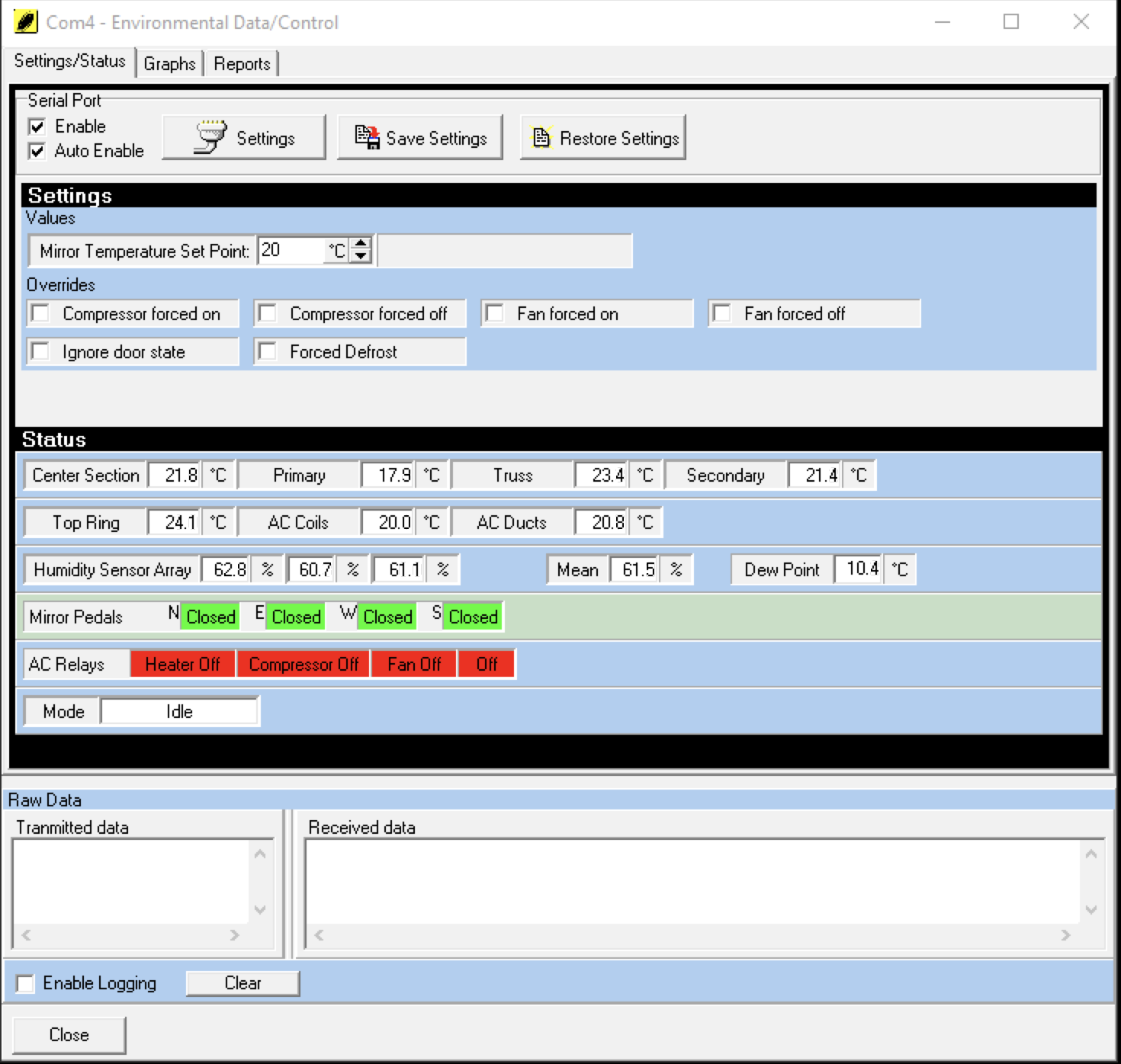
The user interface for environmental monitoring and control can be accessed from Options>Environmental Data/Control
on the TCS Control System GUI. This will bring up the window seen
in Figure 10-2, below. Typically, this window is left open on the
desktop.
Serial Port settings should load automatically as long as "Enable" and "Auto Enable" are checked (default). If for some reason the settings are lost, they can be entered by clicking the "Settings" button. Serial Port paramters are:
Just ignore the warning that the port is not available. With
the system enabled, functionality can be verified by simply watching
the temperature values. If they update, things are running.
10.4.1 Settings Sub-Window
The settings section of the page provides the user with control
of the primary mirror AC system. Typically, seeing can be
optimized by cooling the mirror 1-2 degrees C lower than the ambient
temperature during the night. A good rule-of-thumb is to check
for the low temperature for the previous night and cool to one degree
lower than that. To enter the desired temperature, enter the
value in the 'Mirror Temperature Set Point" window and hit
<enter>. You should hear a chime. The system will
work to cool the mirror 1C lower than the desired set point before
shitting the AC off. The mirror is then allowed to warm to 1C
above the desired set point before the system turns the AC back
on. This limits the duty cycle, and thusly the wear-and-tear on
the AC system. As an example, if the demand temperature is set to
10C, the system will cool until reaching 9C. The AC will then
shut off and remain off until the mirror reaches a temperature of 11C.
The settings section also provides for a series of override options. Users should never have to force-set any components of the system so these should not be touched.
10.4.2 Status Sub-Window
10.5 Graphical Display of Environmental Parameters
The
second tab on the Environmental Data/Control window provides graphical
displays of any or all environmental parameters. The system
defaults to showing all trends, however some, such as Secondary, AC
Coil and AC Ducts can be de-selected. Whenever the TCS Control
System software is restarted, the plots are wiped from memory and start
new.
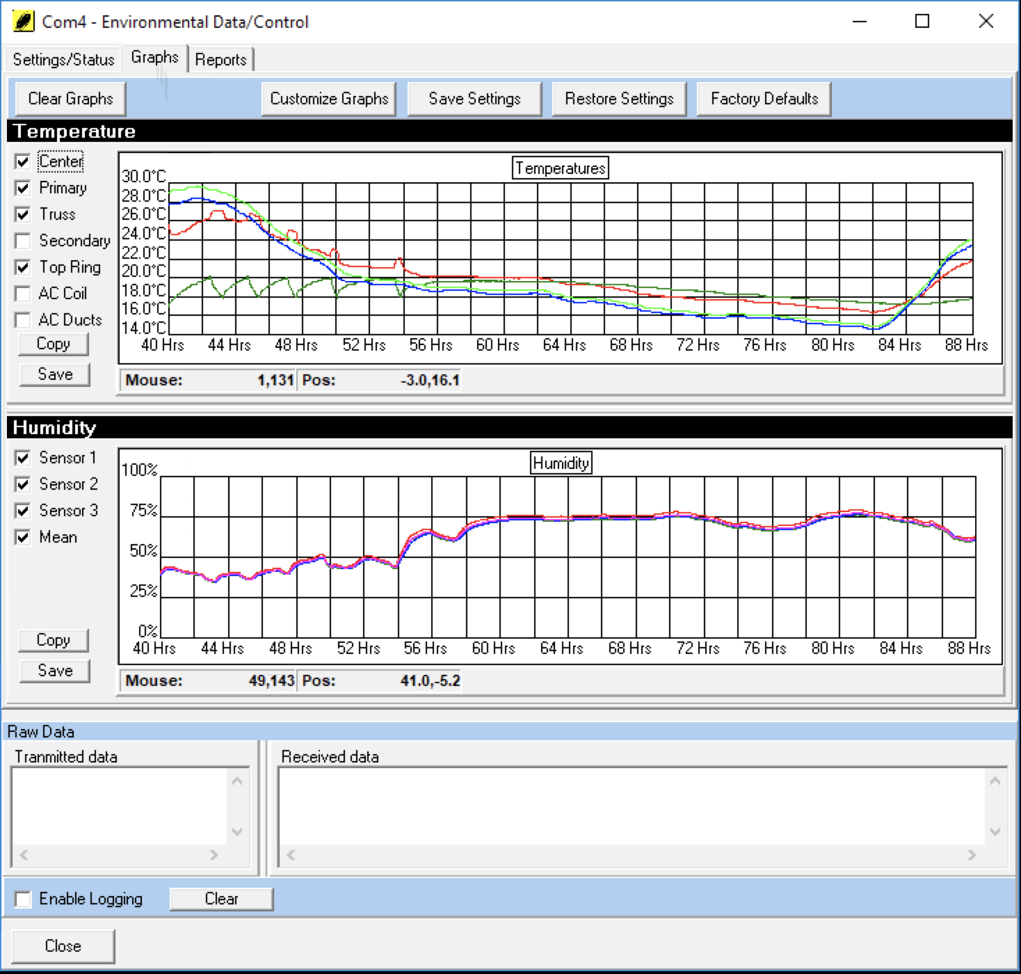
The plots provide a good reference for determining a set point for the mirror cooling.
Note that when observing starts in the early evening, the mirror warms up as it is exposed to the evening air, whose temperature is falling. When set correctly, the primary should remain below the dome ambient for the whole night, being about 0.5 degrees below at the end of the night.
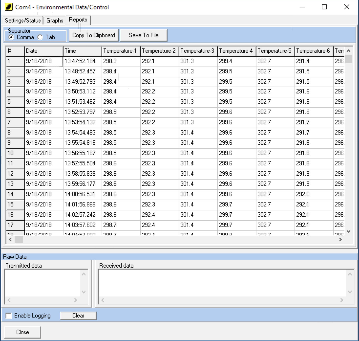
10.6 Raw Data for Environmental Parameters
The last tab on the Environmental Data/Control window provides a spreadsheet display of all raw environmental data. If desired, the data can be saved to file.
| < Prev (Pneumatic System) | Table of Contents | Next (Appendix A) > |