5 Telescope Control System
5.1 Introduction
This chapter describes the operation of the telescope and dome through the Telescope Control System (TCS). The heart of the control system is the TCS computer rack. Figure 5-11 shows the various components in the complete control system. The observer commands the TCS through the Control System Software.
This chapter assumes that you are familiar with the operation of all workstations and the X-window system as described in the previous section.

*While this still presents a good overview, this diagram is not current. Some items have been removed, added, or upgraded. A new flow control diagram will be added when available.
5.2 TCS Computer Rack
While telescope operations are controlled from the Control Room, the "MDC" control electronics and TCS PC reside in the left-most column of the rack
in the computer room. Various components can be controlled
through the MDC, although typically cycling the drives is the only
thing necessary at the start and conclusion of observations.
5.3 Telescope Controller and Monitor
The DFM Engineering, Inc. Control System Interface (Figure 5-2)
is located in the observing room. It, along with the mdm24ws1 work
station, comprise the area where telescope control and data acquisition
will take place. Beyond that, the MDC rack (Figure 5-3), located
in the computer room, contains an array of switches for various
subsystems to the telescope. Theae switches are described
below. Note that typically, the only switch that requires
interaction is the Drives
switch. This DFM System is the culmination of upgrades started in
October of 2017 and running through August of 2018.
Figure 5-3: The MDC Rack
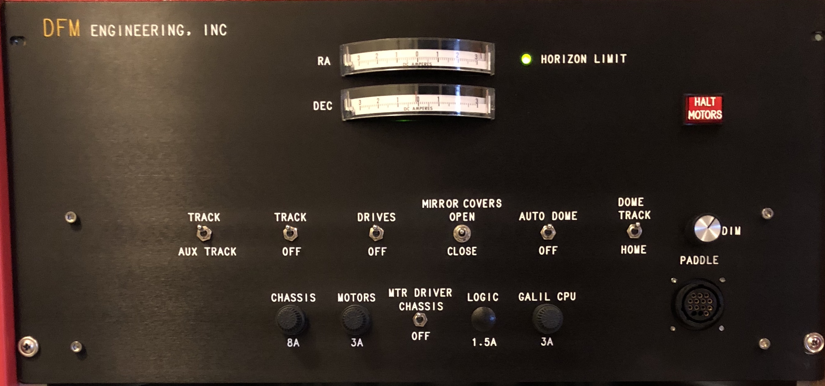
Toggle Switches - Typically, these can all be left in the UP position, although the DRIVES switch can be cycled bracketing observations:
HALT MOTORS: Disengages power to the RA & Dec motor systems in the event of a major failure. Typically, this will not need to be pressed ever.In addition to the status of these switches the Control System is also used to display the following information:

5.4 Telescope Control System
5.4.1 Introduction
The various aspects of the telescope are controlled via software
located on the Win10-based system, as seen in Figure 5-2 above.
Information is shared between the telescope, instrumentation and
JSkyCalc via a background process called tcsBridge.
Startup procedures for the software are described in section 4.3.2; this chapter assumes you are familiar with all of Chapter 4.
5.4.2 Initializing the TCS and tcsBridge
If necessary, load the program tcsBridge (Applications>Telescope
Control>xtcsBridge). However, this is usually already running,
on workspace 4 of mdm24ws1.
5.4.3 Entering coordinates from the keyboard
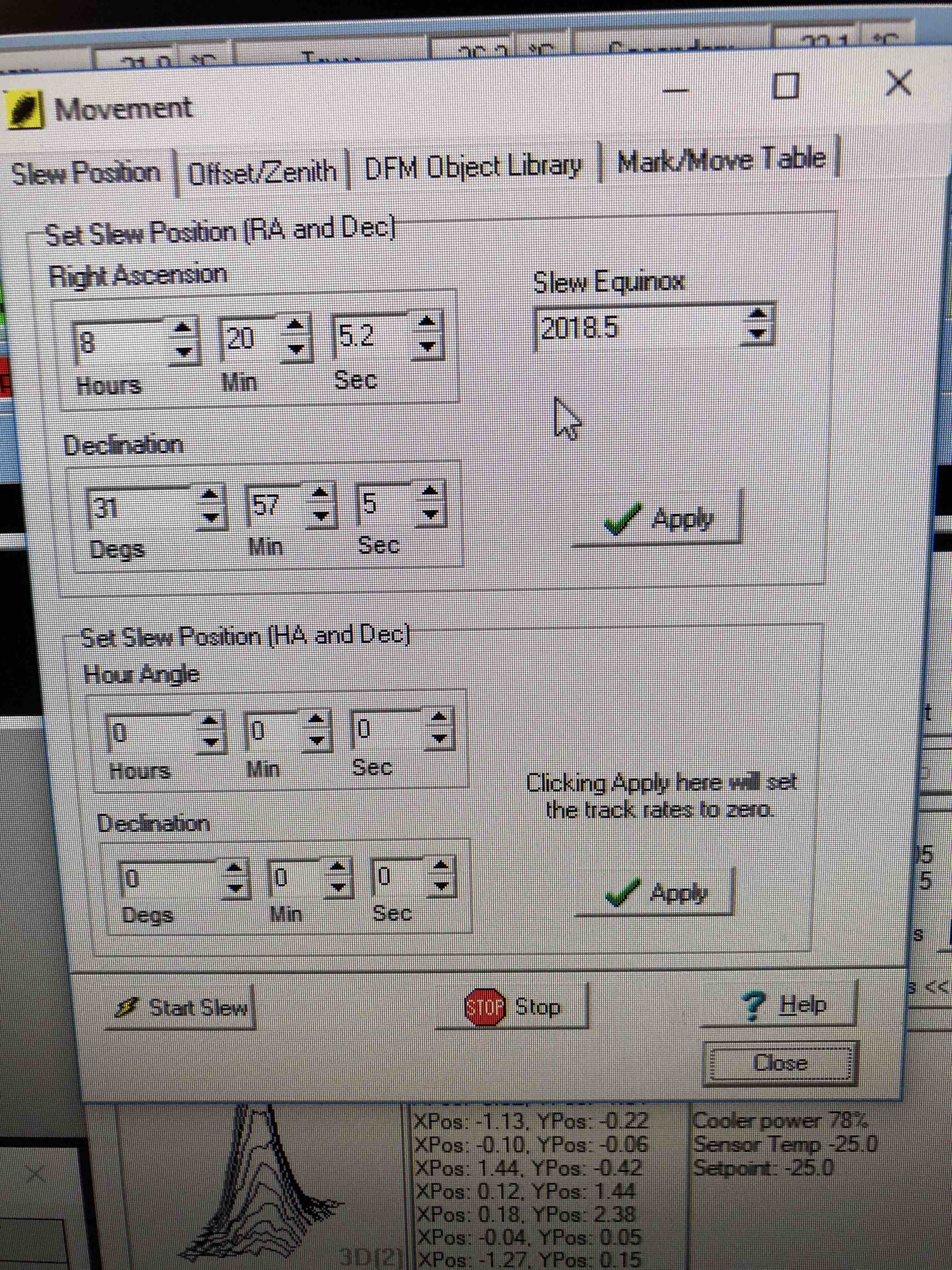
Coordinates can be manually entered by opening the dialog box at Telescope>Movement>Slew Position tab on the control PC. Better yet, load them up through JSkyCalc on mdm24ws1.
Figure 5-5: Manually Entering Coordinates
5.4.4 Entering coordinates from a file
If you have a large number
of
objects or standard stars in your observing program it might be
more efficient to construct a database file. This can be done in
advance and then loaded onto the TCS PC locally via thumb drive.
Object lists can be loaded into the Control System by going to
Telescope>Movement>Mark/Move Table tab. File type is
expected to be filename.mrk.
These can be edited using any standard text editor. A blank form
(blank.mrk) as well as a sample form (one.mrk) can be downloaded here. Using Figure 5-6 as an example, make note of the following: Count should equal the number of objects being added to the list; Namen, RAn, Decn & Epochn correspond to the listing reference, n. Of greatest note, RA & Dec are not input as hh mm ss & deg mm ss
as typical, but instead as decimal values. This requires
conversion prior to creating object lists. A blank conversion
spreadsheet (coord_conv.xlsx) as well as an example version
(coord_conv_samp.xlsx) can be downloaded here
in case assistance is required in converting coordinates.
Properly formatted .mrk files can be uploaded via USB to the TCS Control
PC and placed into a directory, located on the desktop, labelled Target-Lists.
Once the .mrk file is uploaded, click on the 'Load Mark File' button
and load your desired .mrk list file. You should see each object
appear, one per row, on the list. Note that RA and Dec follow
standard hh mm ss & deg mm ss convention in the list.
Figure 5-6: A Sample .mrk File

5.4.5 Setting other encoders
RA, declination and focus readouts are all achieved through absolute
encoders. Therefore, there will be no need to ever set these
values. The dome azimuth and rotator position however use
incremental encoders. In certain situations, such as cycling the
Control System software with equipment not at home positions, it may be
necessary to set these two encoder values. This is done by going
to Telescope>Initialization>Other Positions tab.

5.4.7 Track Rate
Track rates are set from Telescope>Rates>Track Rates tab. To initiate tracking, simply click the "Set Sidereal Rate" button, then click "Apply". This will set the HA track rate to 14.451 Arcsec/sec (and Dec to 0). Users are able to also set an auxiliary track rate. To switch between the two defined track rates, flip the switch between Track and Aux Track on the MDC.
When stowing the telescope, it is necessary to reset track rates to 0 prior to slewing to zenith. To do so, simply enter '0' in the "H.A. Rate" box and click "Apply". You can verify tracking has stopped because the HA value should stop clocking (and RA should start).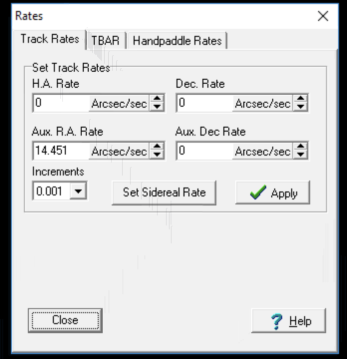
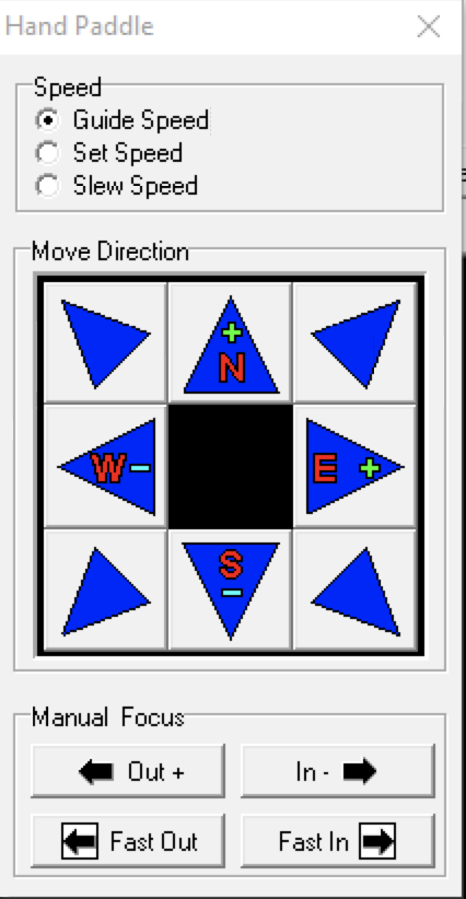
5.5 TELESCOPE HAND PADDLE
Two identical paddles are connected to the telescope. One is in
the observing room, the other is normally hanging to the west side
of the polar axle in the dome. They allow the observer to manually
guide, set, slew and focus the telescope as well as rotate the dome.
Figure 5-9: Telescope Hand Paddle
The following features are available:
Pressing IN (or OUT) together with SET moves the focus ram at a much faster rate.
An absolute encoder displays the position in microns of the secondary ram on the Telescope Monitor.
The TCS software compensates secondary mirror positioning with
reference to changes in temperature. The focus value decreases as the
temperature falls at a rate of roughly 47 microns per 1 degree
C. A routine is provided within the Control System that maintains
proper displacement between the primary and secondary mirrors once
optimal focus is manually determined. While the reference
temperature for the compensating routine can be user-set, it is
strongly recommended that the default selection of "Center Section" be
left as is. See section 5.4.6 above for more information on this.
Focus
the telescope at the start of your first night. Once focused, the
TCS will maintain focus throughout the night. Note that the focus
readout in the TCS display does not change--this is normal and to be
expected. Consider this to be more an indication of secondary
mirror position referenced to the primary as opposed to referencing to
its enclosure. While the compensation will run closed-loop all
night and day, theoretically maintaining proper focal positioning, it
is still worthwhile to verify your focus at the start of each
subsequent night (although don't be surprised if it is already
correct!). It is also worth noting that this system does not take
into consideration any focal changes due to filter changes that may not
be parfocal.
5.6 The Dome
5.6.1 Introduction
The observatory dome is a single skin aluminum hemisphere 10.8 m (425") in diameter, manufactured by Ash Dome. The outside surface is covered with 3M-ScotchR 425 aluminium foil tape to stop over-cooling by radiation at night. The main shutter opening is 2.92 m (115 inches) wide. A drop-out shutter allows the telescope access down to the horizon, although this is limited in practice by the telescope hard limits (Section 5.7).
5.6.2 Dome controller
The dome can be operated manually or under computer control. This is achieved by either selecting AUTO DOME OFF or ON, respectively.
To open the dome:
Special attention must be paid to ice build-up during the winter months. Do not attempt to open the shutter doors if they are iced over. Try turning the icy area towards the sun using the left/right buttons on the hand paddle (with AUTO DOME set to OFF). Often, MDM staff will do this during the day if needed.
To use the automatic dome controller:
The dome should automatically follow the telescope. The TELESCOPE MONITOR should display Auto Dome ON and DOME TRACK. Dome Aximuth (along with Telescope Azimuth) can be found near the bottom-left of the Control System GUI main page. The dead band that the TCS uses to determine when to move the dome is a function of the zenith distance of the telescope. At the zenith, this dead band is 360o.
To close the dome:
5.6.3 Back-up procedure for closing a disabled dome.
The dome shutter doors can only be operated when the contactor box located at encoder position zero makes positive contact with the feet attached to the dome. In the unlikely event that the contactor box fails it will be impossible to open or close the dome from the dome control panel, as described in the previous section.
To open or close the dome when the rotation or contactor box fails:
5.6.4 Occultation of the telescope by the dome near the zenith
The distance from the zenith to the back dome bulkhead (where the shutter motor resides) is only 1.05 m (41.3"). As a result the dome occults when the telescope is pointing within 1.25o of the zenith. The percentage of light lost as a function of Hour Angle and declination is shown in Table 5.1 below.
Table 5-1: Percentage of Light Occulted by Dome Near Zenith
| dDec | Dec. | ||||||
| +75' | 0.00 | 0.00 | 33o 12' | ||||
| +60' | 0.17 | 0.14 | 0.00 | 32o 57' | |||
| +45' | 0.48 | 0.41 | 0.14 | 0.00 | 32o 42' | ||
| +30' | 0.87 | 0.77 | 0.41 | 0.14 | 0.00 | 32o 27' | |
| +15' | 1.34 | 1.14 | 0.77 | 0.41 | 0.14 | 0.00 | 32o 12' |
| +00' | 1.87 | 1.34 | 0.87 | 0.48 | 0.17 | 0.00 | 31o 57' |
| -15' | 1.34 | 1.14 | 0.77 | 0.41 | 0.14 | 0.00 | 31o 42' |
| -30' | 0.87 | 0.77 | 0.41 | 0.14 | 0.00 | 31o 27' | |
| -45' | 0.48 | 0.41 | 0.14 | 0.00 | 31o 12' | ||
| -60' | 0.17 | 0.14 | 0.00 | 30o 57' | |||
| -75' | 0.00 | 0.00 | 30o 42' | ||||
| H.A. | +0m | +1m | +2m | +3m | +4m | +5m |
5.6.5 Obtaining dome flat fields with the white screen.
The dome is equipped with a large white screen for obtaining flat fields. The projectors are no longer in use however. Methods are available for taking twilight sky flats. These are detailed here if interested. MDM may possibly revisit dome flats if demand is great enough, however the engineering required would be extensive as lamps would have to be implemented from scratch.
5.7 MOVING THE TELESCOPE OUT OF THE HARD LIMITS
The TCS has positional
limits to keep the telescope out of unsafe positions. While most
programs require observations near the meridian, there are times when
observations near the horizon are desired.
5.8 WWV TIME
The WWV TIME is used to synchronize the mountain-top computers. The NTP (Network Time Protocol) program uses the U.S. Naval Observatory and a couple of reliable alternative time servers to synchronize all the computers. In practice, sychronization should be to the nearest second or better, depending on the external network connection.
5.9 Observing Room / Dome Intercom
A simple intercom system is used for communications between the observing room and the dome. It is controlled by two independent amplifiers located under the computer bench in the observing room.
Use the following settings to minimize feedback:
| MIC 1 | 6 - 8 |
| MIC 2 | not used |
| PHONE/AUX | not used |
| TONE | 3 |
| MASTER VOLUME | 15 |
| MIC | 2 |
| AUX | not used |
| TREBLE | 3 |
During windy weather you can silence the speaker by turning the black box MIC 1 down.
5.10 Moving Platform
The moving platform inside the dome is used for instrument changes and other engineering tasks. It can also be used when filling the CCD dewar when you are not observing. It is absolutely critical that the platform be lowered all the way prior to moving the telescope or severe damage could occur. Always double-check that the platform is down at the start of the night.
5.11 What to do When Things Don't Work.
Please contact the staff.
| < Prev (Computers) | Table of Contents | Next (MIS) > |