6 The Multiple Instrument System (MIS)
6.1) Introduction
6.2)
The MIS Camera (guider)
6.3) The Multiple Instrument System Control Software, xmis
6.4) The Finder & RETROCAM
6.5) Guider
6.5.1) xmis2 guider parameters
6.5.2) Off-axis guiding for direct imaging
6.6) How to Focus Guider and the Instrument
6.6.1) Focus procedure: direct imaging
6.6.2)
Focus procedure:
spectroscopy
6.7) Filter Wheels and Filters
6.7.1) 4" filter wheel
6.7.2) MDM filter sets
6.7.3) The MDM Johnson UBVRI filter sets
6.8) Technical Reference Section
6.8.1) Guest instrumentation and the MIS mounting plate
6.8.2) xmis2 software configuration (for staff use only)
6.1 INTRODUCTION
The Multiple Instrument System (MIS) comprises three discrete and independent modules which can be used with a suite of analytical instruments: finder, guider and filterwheel (Figure 6.1).
The Finder module is equipped with an Apogee CCD for imaging (RETROCAM). It is worth noting that the Finder module is no longer equipped with a video camera as shown in Fig. 6-1. The finder module also contains spectral calibration (Ne, Ar, Hg-Ne & Xe) and flat field lamps.
The OSU Buckeye filter wheel module, which also contains a shutter, is used with imaging detectors and some spectrographs when employed as image reduction systems.
The MIS modules are attached to the instrument rotator (Chapter 8) and thus, changing the rotator angle will alter the orientation of the finder and guider fields.
The operation of the MIS is linked with several other units that must be turned on for acquisition and guiding (Figure 6-2). An FLI CCD is used for auto-guiding, connected via USB to the Windows-based TCS PC in the computer room.The MIS modules communicate through the MIS control crate, which is located in the right center instrument rack of the computer room. The front panel contains simply a power switch while a bank of fuses are located on the back panel.
Figure 6-1: Finder-Guider-Filter Wheel Optics
Figure 6-2: MIS Control Schematic
6.2 The MIS Camera(guider)
The guider is equipped with a low-light-level Finger Lakes Instrumentaion (FLI) CCD that gives a real time display on the Guider PC. Numerous user-settings, such as CCD temperature, binning, exposure rate, etc. can be modified as the observer sees appropriate.
The guide camera has a "wall-wart" power supply, mounted on the instrument rotator flange. These units are normally left ON; they must be powered down when the camera cables are disconnected to avoid damage to the CCD.
Note that the display orientation changes with position angle of the instrument rotator (Chapter 8).
Figure 6-3: xmis2 GUI

6.3 The Multiple Instrument System Control Software, xmis2
The MIS control crate is connected to the observer's console (mdm24ws1), where commands to operate the various slides, lamps and filter wheels are entered through the xmis2 GUI (Figure 6-3). When the filter wheel is not used, the information on the filters is not displayed in the window.
This chapter assumes you are familiar with all of Chapter 4. Start-up procedures for the software are described in section 4.3.4.
When the software is loaded, a large red box with the word INITIALIZE appears. Click on this to initialize communications with the MIS control crate. Use the xmis2 SETUP menu to initialize or quit the software at any time. If one or more of the modules fails to initialize using xmis2, but continues after pressing the reset button on the control crate, quit the GUI and power cycle the MIS unit in the computer room.
6.4 The Finder & RETROCAM
The Finder is used for spectroscopic calibrations or for lamp-based
flat fielding. If the Finder is set to the "IN" position, then it
is in the optical path and ready for calibration use. For on-sky
observing, the Finder is set to the "OUT" position.
For
spectroscopic calibration, move the Finder "IN" and choose the
appropriate lamp(s). If the lamp button is highlighted in green,
it is on. Make sure that the Guide Probe is not blocking the slit
[Guider: S (10600,0)]. For best results, darken the environment
to prevent "light leaks"--close the doors, turn off the lights and
close the dark hatch. Remember to turn off the lamp(s) when
done. This can be done by either clicking the appropriate lamp
button a second time, or by simply clicking the All Off button.
Placing the Finder "IN" also allows for observations to be taken with RETROCAM. RETROCAM is a science-quality optical CCD camera. It is available for use with all of the observatory's primary instruments. It uses the MIS finder mirror, which obscures the science field of the primary instrument. Thus while RETROCAM can be used with most primary instruments, the two cannot be used simultaneously. The finder mirror has been resized such that a ~100 arcmin2 horseshoe-shaped guide field is available around the perimeter of the MIS aperture. Typical uses for RETROCAM include:
- An imager for targets of opportunity (SNe, GRBs, microlensing events, etc.)
- Spectroscopy and photometry of the same target
- Finder camera for the MDM 2.4m
- Spectroscopic calibration.
RETROCAM is typically powered off. If desired, please request it be set up.
6.5 GUIDER
The FINDER mirror must be OUT to allow starlight to reach your instrument, but can be used with RETROCAM (see RETROCAM User Guide)
An autoguider is available and is described in Section 7, which assumes that you are familiar with the contents of this section.
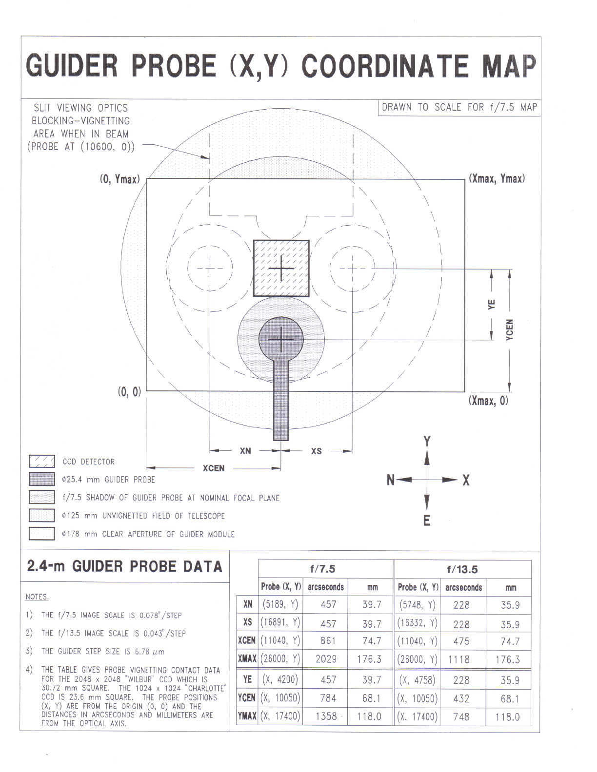
The guider has a diagonal probe whose minor axis is 25.4 mm. The probe can move in x and y directions as specified in Figure 6-4.
The probe has three basic positions accessible through the Preset pop-up menu:
- Origin: probe completely out of beam
- Center: probe looking up on the main optical axis
- Slit: probe looking down at light reflected off the slit plate
6.5.1 xmis2 guider parameters; preset pop-up menu
The probe can be moved to the first three positions by selecting the destination in the xmis2 Preset pop-up window. The coordinates of the guider probe, together with the message [O], [C] or [S] are displayed in the xmis2 window:
|
Origin: |
Guider: O |
(0, |
0) |
|
Center: |
Guider: C |
(11040, |
10050) |
|
Slit: |
Guider: S |
(10600, |
0) |
Units: probe
The default coordinates, given in motor steps where 1 step moves the probe 0.078 arcseconds at f/7.5 (and 0.042 arcseconds at f/13.5, obsolete).
Units: arcsec
The scale is set to 0.07839 to display the probe coordinates in arcseconds at the f/7.5.6.5.2 Off-axis guiding for direct imaging.
The probe can move off-axis in x and y directions as specified in Figure 6-4.
Figure 6-4: GUIDER PROBE X-Y COORDINATE MAP
There are two ways to move to an off-axis position, using either absolute or incremental instructions.
X pos: Y pos:
To move the probe in absolute coordinates, place the mouse in the X pos box, type in the desired value and press enter. You will see the message "probe moving" and then the new position will be displayed. Repeat the procedure for the desired Y pos.
dX: dY:
To move the probe by an incremental amount place the mouse in the dX: box and enter the desired amount of movement. Repeat for dY:. 1000 counts will move a star about halfway across the field. Positive numbers move the star right (dX:) and up (dY:) (assuming rotator angle of zero) and negative numbers go the opposite way.
Stop
If you are scanning for a guide star and you see a suitable object moving across the field click on the Stop box to arrest the motion.
6.6 HOW TO FOCUS THE GUIDER AND YOUR INSTRUMENT
This section assumes you are familiar with the preceding sections. The procedure is different for direct imaging and spectroscopy. Once everything is aligned and focused you can note the field centers.
6.6.1 Focus procedure: direct imaging.
- Acquire a bright star.
- Bring your instrument (telescope) into focus:
o Make sure the Finder is Out.
o Move the guide probe to Center through the Preset pop-up menu.
o Center the star on the guider display then move the guider to the origin.
o Center the star on the detector. It should be close since you have already centered on a center-oriented guider.
o Focus the telescope by moving the secondary mirror:
Use Telescope>Misc>Focus tab or the telescope hand paddle.
IN drives the focal plane UP
OUT drives the focal plane DOWN
SET + IN or SET + OUT gives a rapid focus change
1 focus unit = 1 micron motion
- Bring the guider into focus:
o Move the guide probe to Center through the Preset pop-up menu.
o Focus using Guider_Focus.exe, found on the TCS PC desktop. Clicking STOP will halt the program. Click the white arrow, as seen in the images below, to restart the program.
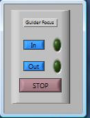
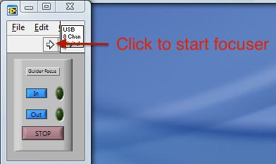
o If you cannot achieve desired focus, let the MDM staff know. Even if your focus produces donut-shaped stars, the guide system should still work effectively enough (mmm... guide donuts) for science.
6.6.2 Focus procedure: spectroscopy.
1. Acquire a bright star.
2. Focus the telescope on the slit plate
o Focus the telescope by moving the secondary mirror:
Use Telescope>Misc>Focus tab or the telescope hand paddle.
IN drives the focal plane UP
OUT drives the focal plane DOWN
SET + IN or SET + OUT gives a rapid focus change
1 focus unit = 1 micron motion
- Focus the spectrograph:
o If time permits, the staff will focus the instrument for you. However, in the event of telescope problems, or even double-instrument changes, there may not be adequate time to run through the focus routine prior to your arrival. It's good to read through the manual(s) specific to your instrument and have a working knowledge of what is required to focus the instrument in advance.
6.7 Filter Wheels and Filters
6.7.1 4" filter wheel
The OSU "Buckeye" filter wheel can be used for any direct-imaging setup (MDM or 4k CCDs). It is controlled via the xmis2
GUI interface. It is a 12-position filter wheel, holding up to 11
4"-square filters at a time (slot 12 is usually reserved as an open
pass-through). Typically, 2"-square filters can also be mounted
in modified filter holders as well. MDM staff only should perform any filter changes.
6.7.2 MDM filter sets
4" UBVRI filter set: In 2004 MDM received a set of four-inch square filters for use in the new filter wheel. They were supplied by Custom Scientific, Inc. to the same specifications as the 1999 2" UBVRI filters.4" DES-i, z, Y
4" SDSS-g, r, i
2" h-alpha
2" 893/13.6
2" Gunn-u, g, v, r, i
2" Kitt Peak-R, I
Transmission curves and other data for filters can be found here: MDM filters for CCD imaging. If you request any of these filters they will be installed for you by the staff. If you have special requests for filters that aren't listed here, ask MDM staff in advance and we will see what might be available.
6.7.3 The MDM Johnson UBVRI filter sets
Two UBVRI filter sets, four inches square are available. All filters will be installed for you by the staff.
The prescription of the glass used for these sets, designed by Jim Schombert while he was at Michigan, is as follows:
|
FILTER |
Glass |
|
U |
Schott UG-1, WG-280, Hoya CM-500 |
|
B |
Schott BG-12, BG-39, GG-385 |
|
V |
Schott GG-495, BG-18 |
|
R |
Schott OG-570, KG-3 |
|
I |
Schott RG-715 |
Unfortunately, they are of different thickness and not parfocal. The filters were cemented, polished better than 50 microns, and MgFl2 anti-reflection coated by Fish-Schurman in New York. Tracings of the filters (Figure 6-5) show that this set is similar to the Harris formula used on Kitt Peak, with some noticeable exceptions:
The U filter does not use a liquid CuSO4 cell, but rather a new red blocking glass called CM-500 from Hoya optical.
The B filter has been cut sharper at the red side than the original Johnson formula in order to more clearly separate the relative fluxes in the B and V bands. This produces slightly better color information in galaxies.
The R filter has a longer tail than the original Johnson R, a result of the lack of good glass beyond 6000 angstroms. It has a red leak at l > 1.05 mm.
The I filter is an interference-type filter (Cousins I) instead of the old-style Johnson I that had its exact response determined by the red-cutoff of the CCD response.
Figure 6-5: Schombert Filter Set Transmission Curves
6.8 Technical Reference Section
6.8.1 Guest Instrumentation and the MIS mounting plate
The finder, guider and filterbox modules of the MIS all have the same basic 12 mounting holes (Figure 6.6). These holes, 0.625 DIA, take reducing bushings and nuts. These are available in stainless steel and nylon. An electrical isolating spacer, made of G10, may also be available.
The vertical height of each box is shown in Figure 6.1; a variety of back focal distances can be accommodated by using a combination of the modules:
|
Modules used |
remaining back focal distance (inches) |
|
|
|
|
none |
15.72 |
|
Finder |
7.25 |
|
Finder + Guider |
3.00 |
|
Finder + Guider + Filter wheel |
0.50 |
If the MIS is not used at all, the instrumentation can be mounted directly on the instrument rotator (Section 8).
The diameter of the central hole in the FINDER and GUIDER boxes is 177.8 mm (7.0 inches), and the unvignetted field diameter of the telescope at f/7.5 is 125 mm (5 inches). The guider probe and the slit-viewing optics both vignette this field (Figure 6-4).
The slit viewing optics were designed for use with a focal plane 63.5 mm (2.50 inches) below the guider box. The optimal focal plane of the telescope, however, lies 76.2 mm (3.00 inches) below the guider. The slit viewing optics can be adjusted to accommodate slit planes from approximately 50 to 81 mm (2.0 to 3.2 inches) below the guider box. The FILTER WHEEL has, in addition to the 12 mounting holes around the perimeter which take the reducing bushings, 8 holes tapped 1/4- 20 as shown. The central hole is 2.25 inches in diameter.
The maximum total weight of the instrument depends upon its distance and distribution from the instrument rotator, and is approximately 500 pounds (225 kg). A moving platform allows heavy instruments to be raised for attachment to the telescope. Please consult the staff at an early stage if you plan on bringing out your own instrumentation.
Figure 6-6: MIS Mounting Plate Dimensions
6.8.2 xmis2 software configuration (for staff use only)
Staff notice for instrument changes: The xmis2 software needs to know which of the three MIS modules are installed. The telconfig script is used to setup both the TCS and MIS configuration for a given telescope and instrument combination. See the Startup Guide for details.Updated: 2018Sep19 (Galayda/MDM)